
Lunar Lander Controller
For the 1st Tangible Interaction Workshop assignment, we were asked to make a controller for a browser version of the classic arcade game Lunar Lander.
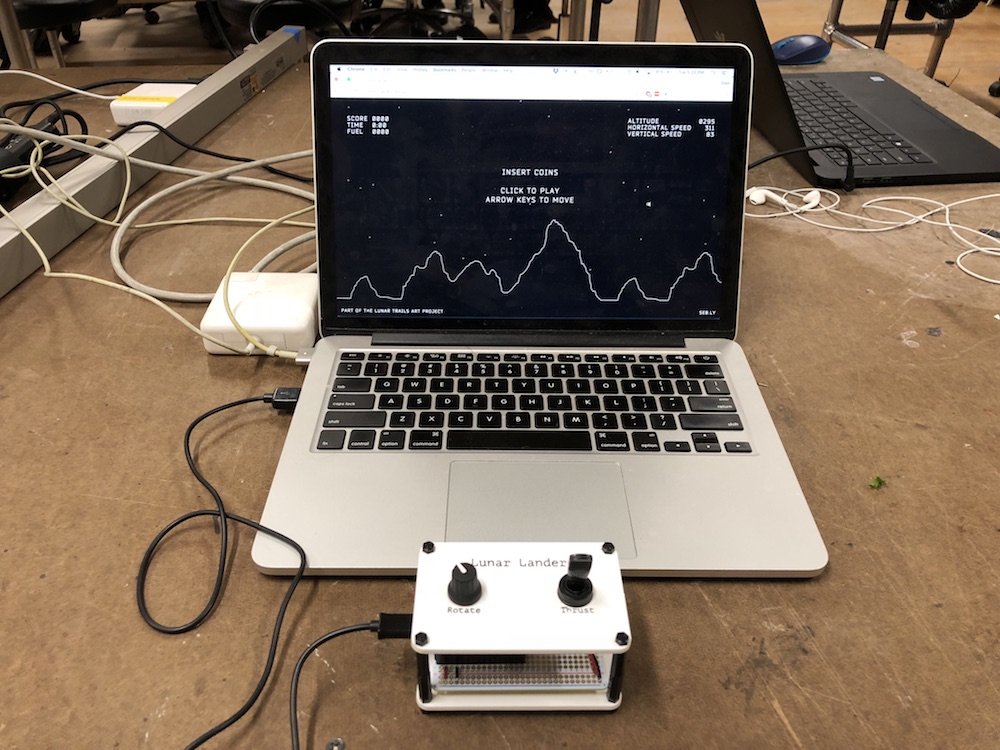
The controls for this version of the game are:
- Click the left mouse button to start.
- Rotate clockwise and counter-clockwise using the right and left arrow keys, respectively.
- Fire the thruster using the up arrow key.
Components
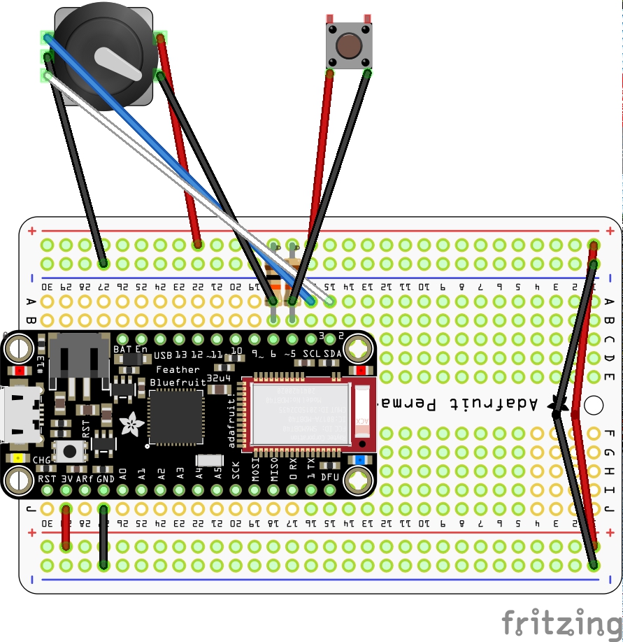
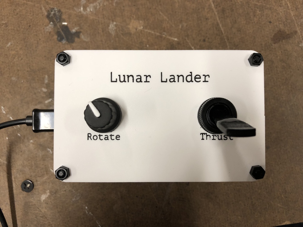
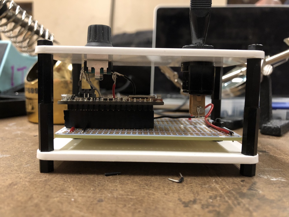
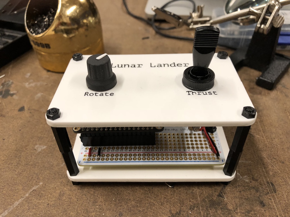
I chose to use a momentary toggle switch to control the thruster and a rotary encoder with a built-in momentary switch to control the rotation and handle the mouse click. I needed a microcontroller that could be programmed to be a USB HID device in order to act as a keyboard and mouse, so I went with an Adafruit Feather 32u4 that I had lying around from a previous project. I also used an Adafruit Perma-Proto Half-sized Breadboard PCB for the circuit, and used female headers to avoid soldering the microcontroller directly to the perfboard.

Enclosure
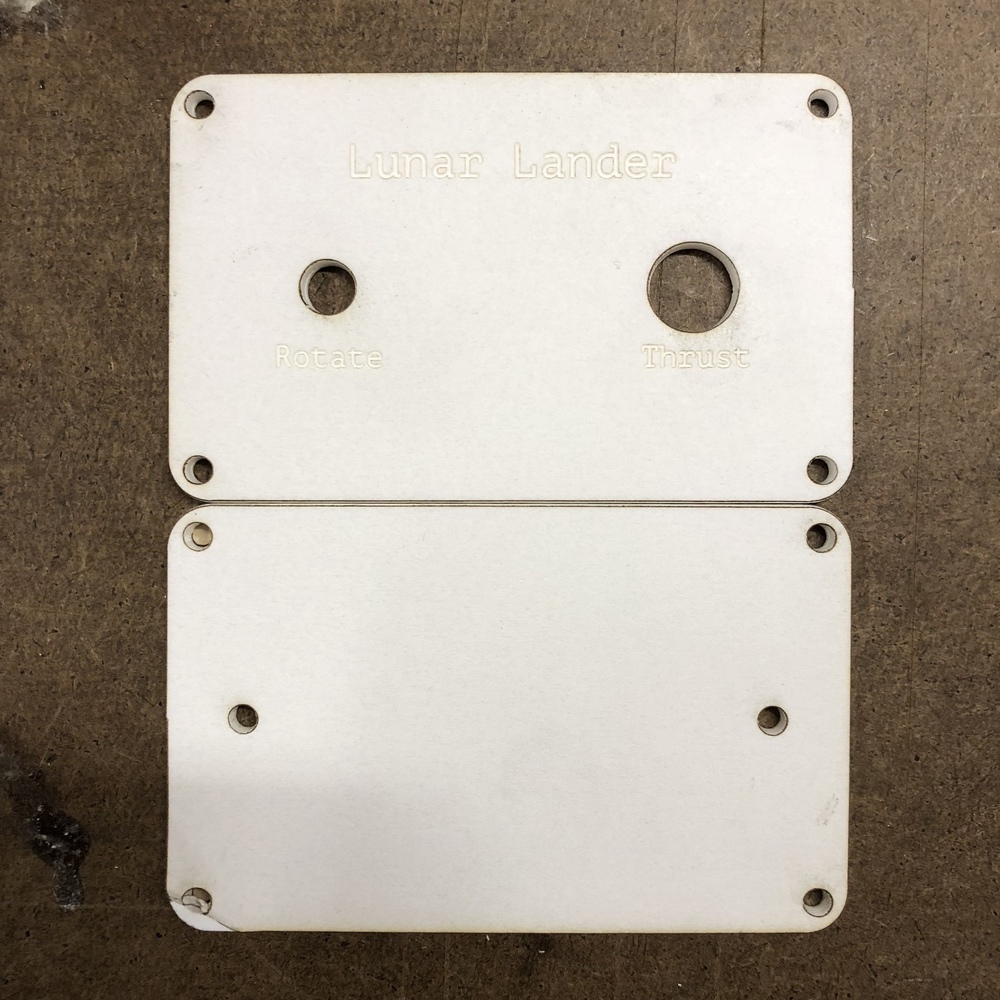
Once I’d sourced my components, the next step was to design the interface and enclosure. I decided to go with a standoffs-and-panels approach (as described in the Intro to Fabrication notes), using black nylon hex standoffs and 1/8” white matte acrylic. I designed the panels in Vectorworks, then cut them out on the 75 Watt Epilog laser cutter.
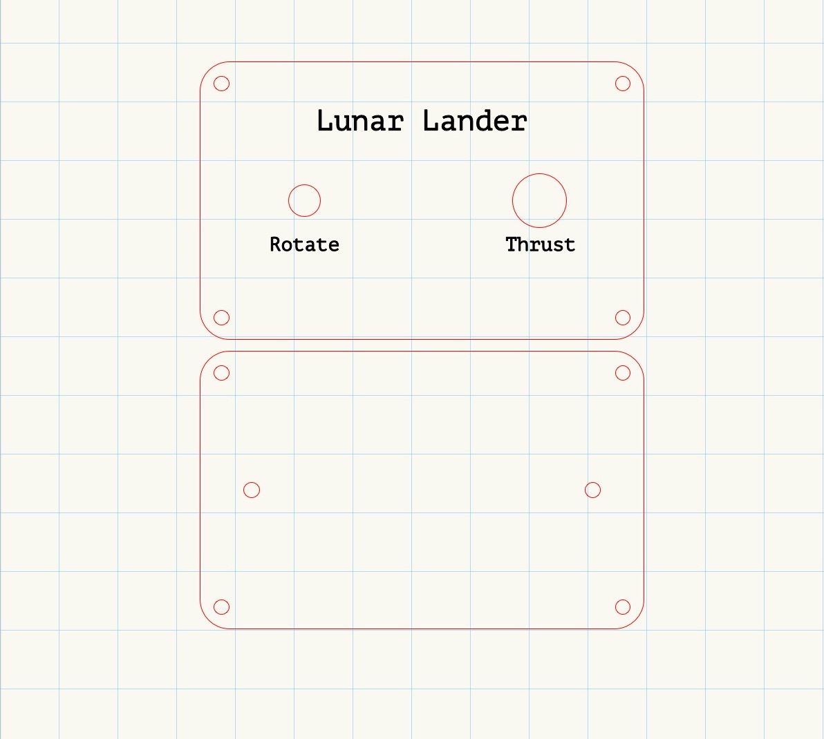
Before I cut the panels in acrylic, I did a test cut in cardboard to make sure that my measurements were correct.
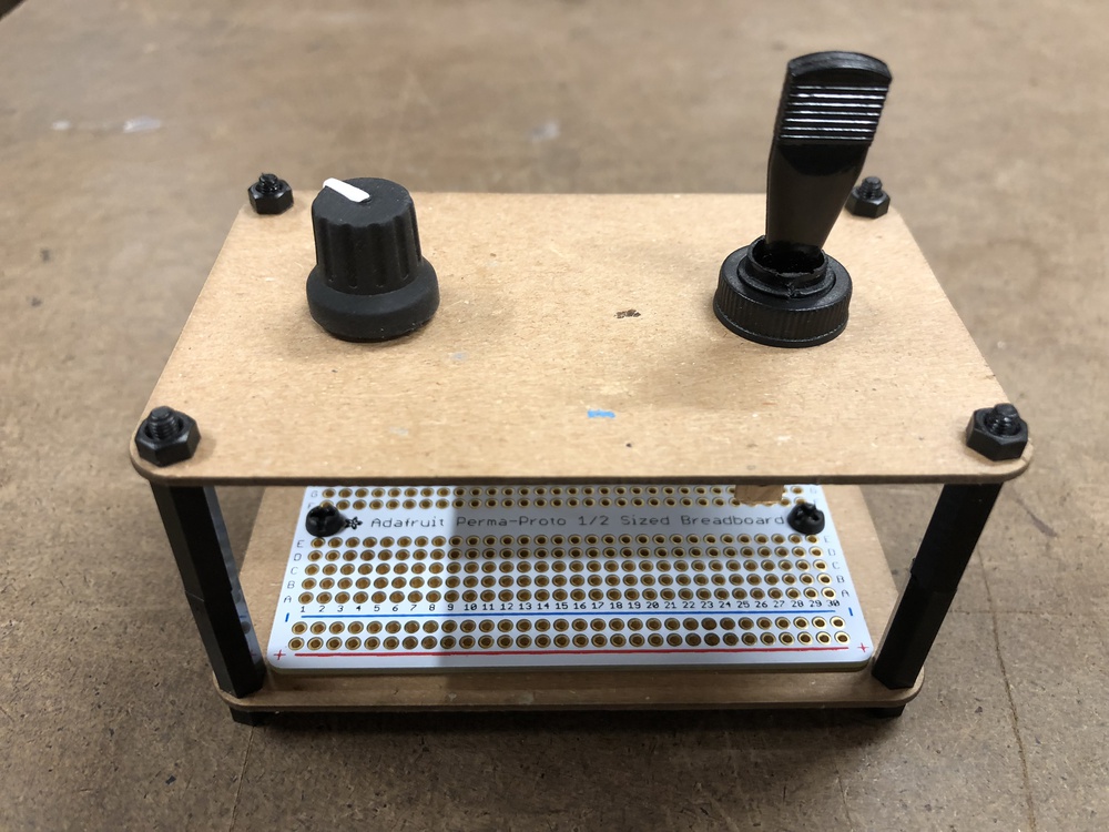
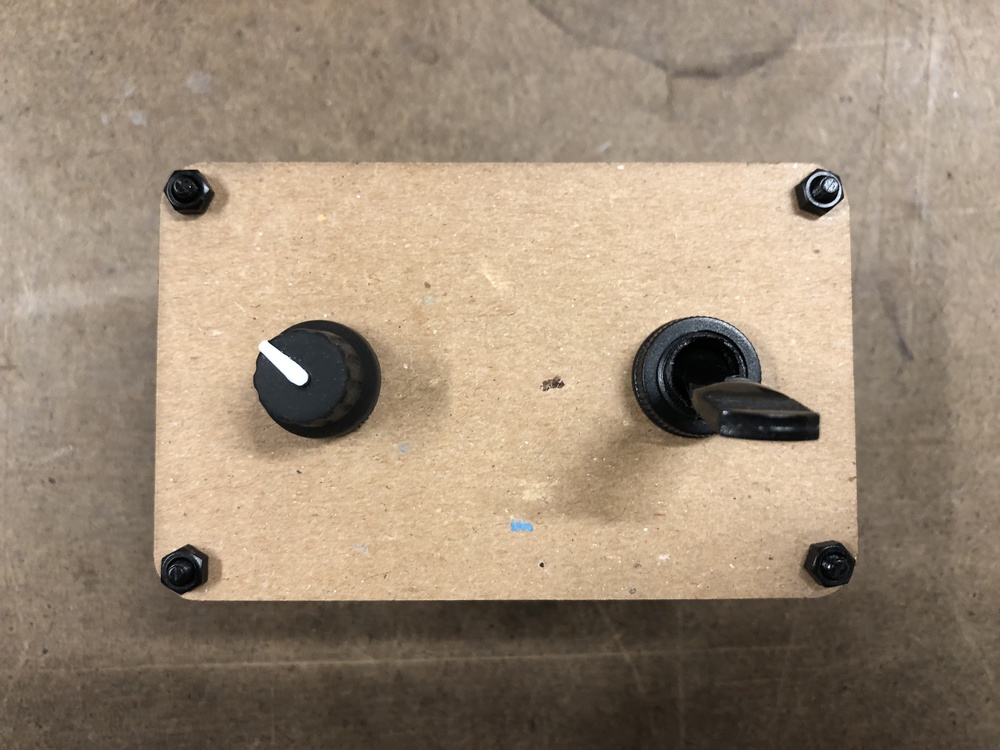
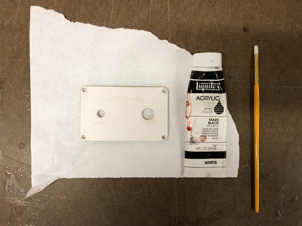
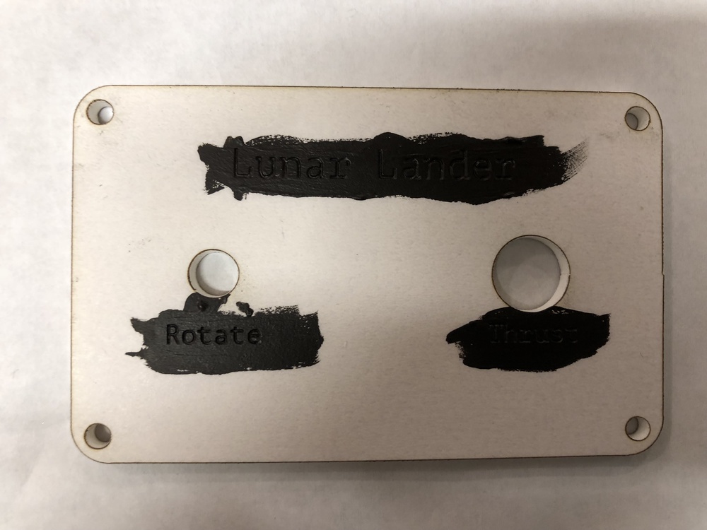
Once I was sure that everything checked out, I cut and etched the panels in the white matte acrylic. I left the paper on the acrylic when etching, so that I could paint over the etched text in black acrylic paint later.
Circuit
At this point, the fabrication was pretty much done, and it was time to work on the circuit. First, I soldered wires to my components and prototyped the circuit on a breadboard. I made sure to use pins 2 and 3 for the rotary encoder, as the Encoder library works best with hardware interrupt pins, and pins 2 and 3 are both interrupt pins on the Adafruit Feather 32u4. Once I was sure everything was working, I soldered the wiring to the Perma-Proto PCB and assembled the controller.
Putting it Together
Code
The code for controlling the up arrow key and left mouse click using the two momentary switches was pretty straightforward. The more complicated part was mapping the rotary encoder’s rotation to the left and right arrow keys. Initially, turning the rotary encoder would only rotate the lander by a small amount, because each turn of the knob only “pressed” the corresponding arrow key for a short amount of time. The solution to this was to add a short delay between pressing the key and releasing the key, with the length of the delay proportional to the amount of rotation generated by each turn.
Playtesting
Files
Arduino source code
Illustrator file for laser cutting the enclosure
Fritzing sketch for the circuit diagram
Mounting a Motor
For the 6th of Intro to Fabrication, we were asked to make a project that involved mounting a motor. I chose to combine this assignment with my final project for Designing for Digital Fabrication, a motorized kinetic art installation that uses the Moiré effect to create a looping animation. The motorized aspect of the piece involves a geared DC motor turning two dowels via timing belts and pulleys.
My collaborator Barak Chamo and I weren’t able to entirely finish the project in time (we still need to attach a transparency to the dowels that has vertical lines that create the Moiré pattern), but we were able to mount our motor and get the dowels turning with the timing belts.
Inspiration
This project was heavily inspired by Takahiro Kurashima’s Poemotion books.
Materials
- 3/4” plywood
- 5/8” wooden dowels
- 5mm aluminum rods
- 12V 20RPM geared DC motor
- 8mm to 5mm shaft coupler
- Timing belts and pulleys
- 1/8” white translucent acrylic sheet
- Black acrylic paint
- M4 20mm screws (for mounting the motor)
- 8-32 3” wood screws (for fastening the frame together)
- Air conditioning isolation foam
Process
There was a lot of digital fabrication that went into this project – the frame was cut on the CNC router, the acrylic sheet was laser etched and cut, and we 3D printed couplers that connected the wooden dowels and the aluminum rods (would definitely not recommend doing that last one).
CNC-ing the Frame
Etching and Painting the Acrylic
Motor Control Circuit
Mounting the Motor in the Frame
Result
Two Materials
For the fifth week of Intro to Fabrication, we were asked to make a project using two materials, neither of which could be acrylic or plywood. I ended up making an origami crane out of paper and a thin brass sheet.
Materials
Process
First, I folded the origami paper into a crane. Thanks to Jenna Xu for teaching me the folding pattern!
Folding the Crane
Attaching the Brass
Once the crane was folded, I cut some triangles out of the brass sheet and used epoxy to glue the brass pieces to the wings and beak of the crane.
Before gluing for real, I tested the epoxy with some scrap paper and a small piece of metal.
One issue that I ran into was that the epoxy left some ugly marks on the brass and paper. If I were to do this again, I would experiment with ways of covering the paper/brass while the epoxy set.
Guitar Pedal Enclosure
For the fourth week of Intro to Fabrication, we were asked to make a project enclosure, and…I went a little crazy with this assignment. In class, Ben mentioned powder-coated aluminum guitar pedal enclosures as a possibility, and I got really excited, because I’ve been playing guitar for most of my life, and it never occurred to me that I could make my own effects pedals.
I decided to make a 4-track audio looper pedal. The interface includes 4 stomp switches to control recording and playback for each loop track, 4 NeoPixel LED rings to show playback progress for each loop, a volume knob, another stomp switch for turning the pedal on and off, and an LED for indicating on/off status. I also intended to add two 1/4” mono audio jacks for input and output and a 9V power jack, but I ran out of time and wasn’t able to drill the necessary holes before class.
The case of the enclosure is powder-coated aluminum, but the lid of the enclosure is laser-cut acrylic, because I wanted to prototype my interface design before irrevocably drilling any holes in the powder-coated aluminum lid.
I consider this project half-done – I got overly ambitious with this, especially because I had to go home for Thanksgiving break and didn’t have access to the shop until the Monday before class.
Files
Illustrator file for laser cutting/etching the enclosure lid
STL file for 3D printing the NeoPixel ring mount
UPDATE: I redesigned the NeoPixel ring mount to prevent the ring from rotating.
Materials
- 1 Blemished Powder Coated Aluminum Enclosure
- 1 3PDT True Bypass Pedal Switch
- 4 DPDT Pedal Switches
- 1 10K Potentiometer
- 1 Pointer Knob
- 1 Panel Mount DC Power Jack
- 2 Panel Mount Mono 1/4” Audio Jacks
- 4 Pack of Rubber Feet
- 1 5mm LED Bezel
- 1 5mm Red LED
- 4 Adafruit NeoPixel 16 LED Rings
Process
The aluminum enclosure came with a set of countersunk screws, but I didn’t want to use those with an acrylic lid as that would require drilling into the acrylic with a countersink bit. Instead, I decided to use socket cap hex screws which would hopefully sit flush with the acrylic lid. I measured the original screws with a caliper (although now I know that I should have used a thread pitch gauge) and found that they were 10mm M3 screws, and then I went to Home Depot and bought the equivalent socket cap screws.
3D Printing
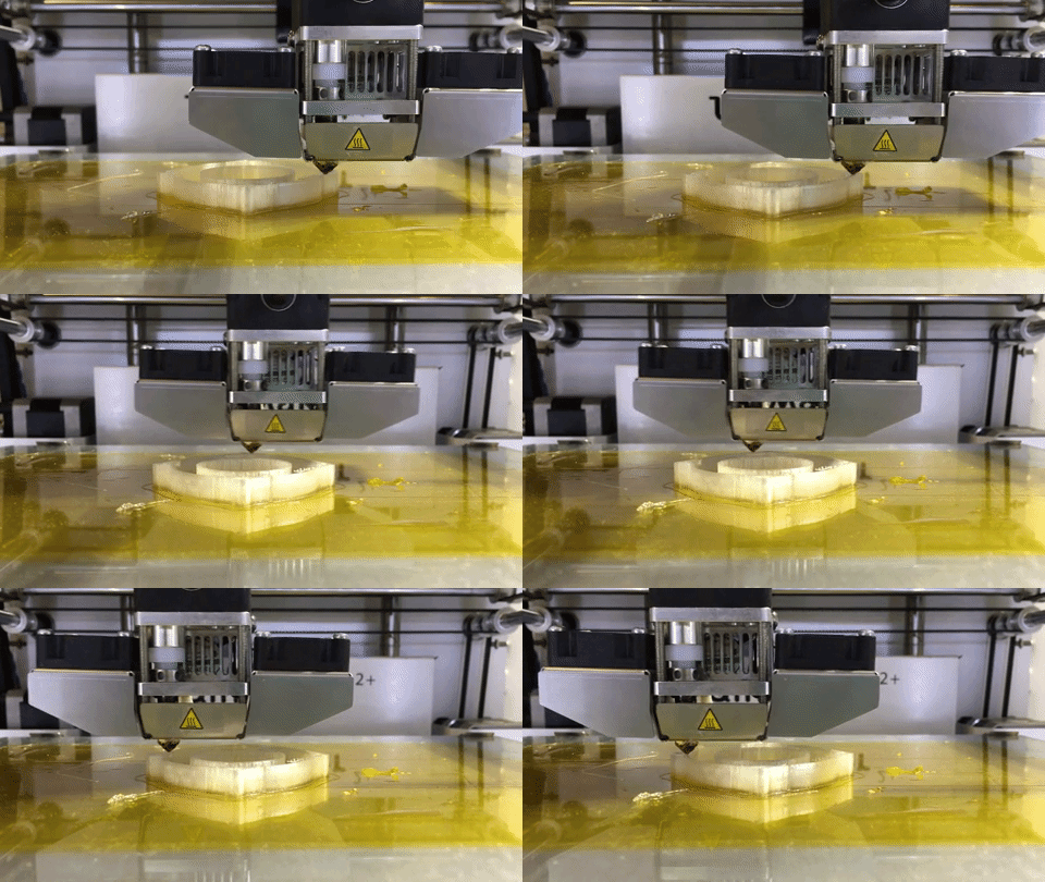
While waiting for my components to arrive, I started working on a 3D printed mounting bracket for the NeoPixel LED rings. I wanted to mount the NeoPixel rings underneath the lid, to prevent damage to the LEDs when a user steps on the pedal switches. I adapted these two designs from Thingiverse into a model with M3 screw holes, to re-use the screws that I’d already bought.
![]()
![]()
Designing the Interface
Once all of my components arrived, I measured the dimensions of the enclosure lid using a caliper, as well as the diameters of the switches, potentiometer, and LED bezel. I also found a data sheet for the enclosure that I checked my measurements against. I then used these measurements to make a laser cut design in Vectorworks.
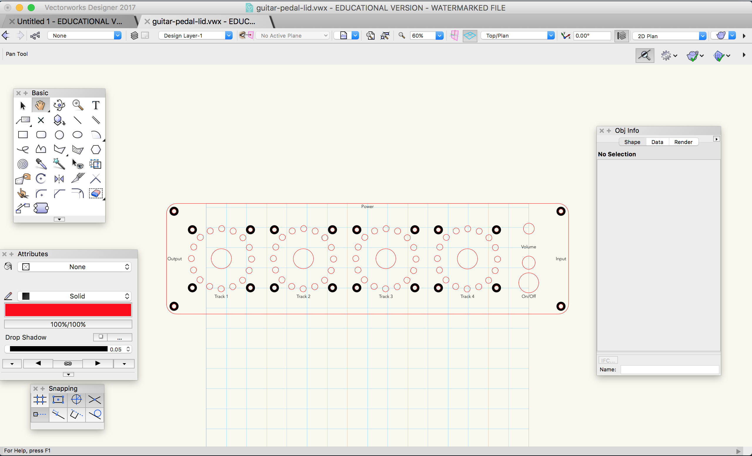
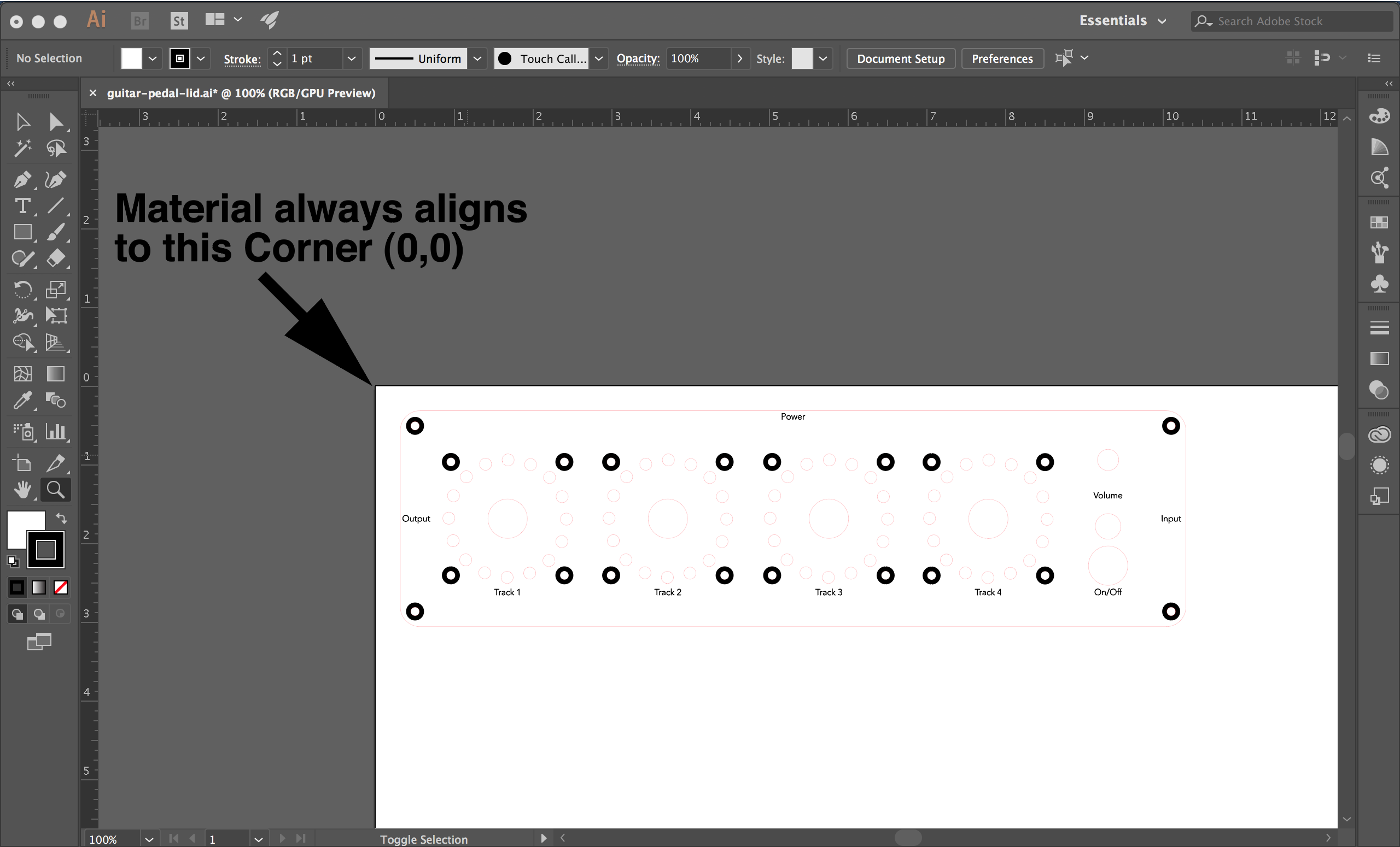
Laser Cutting
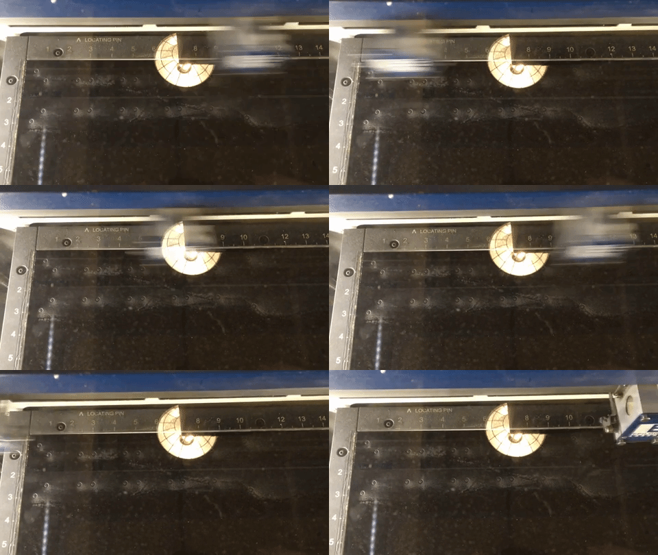
I had to do a few test cuts in cardboard in order to get the placement of all of the screw holes exactly right.
Once I had all of the holes positioned correctly, I did a cut in black acrylic. One mistake that I made here was to take the paper off of the acrylic before cutting & etching – this led to smudges from dust created by etching. In my design, I intended to etch a ring around each screw hole to allow the screw heads to recess into the lid, but in practice I found that the etching was time-intensive and didn’t lead to great results.
Putting it Together
Finally, I attached all of my panel-mount components and my NeoPixel ring mounts.
Next Steps
My next steps for this project would be to drill holes in the aluminum enclosure for the audio and power jacks, to playtest the interface design, to redesign the NeoPixel mounts to prevent the rings from sliding around, and eventually to re-do the interface in the original aluminum lid.
Laser Cut Box with Rounded Corners
For the third week of Intro to Fabrication, we were asked to laser cut something, and I decided to try using living hinges to make a box with rounded corners.
References
I adapted my design from a laser cut box designed by Oomlout. My main modifications were trimming down the top and bottom parts so that they were flush with the sides, removing all the extraneous holes, and adding a locking mechanism to help keep the box closed.
All of Oomlout’s files
Oomlout’s DXF file that I based my design on
I also found this article on living hinges useful for getting a better understanding of how living hinges work.
Files
Illustrator file for laser cutting the box
Materials
My plan was to prototype my design in 0.1” 30-ply chipboard, because it’s very cheap ($1.83 at Blick!), lightweight, and sturdy, and then switch to 1/4” plywood for the final iteration. However, I ran into problems trying to cut living hinges into my plywood – the hinges snapped as soon as I bent them. I suspect that 1/8” plywood would work better, but I didn’t have enough time to get more materials and try to cut again. That said, I’m quite happy with how the chipboard prototype turned out.
Tools
Process
The first step was to modify Oomlout’s original Illustrator file, which I chose to do in Vectorworks because I’m a little more comfortable with it than Illustrator.


Because the chipboard was so dense, it took 3-4 passes with the laser to cut all the way through. My settings for the 75 watt laser (adapted from the settings for mat board) were 30 speed, 75 power, and 50 frequency. I initially tried 40 power, but found that that was nowhere near strong enough to cut through the chipboard. I was a little concerned about getting fires at 80 power, but it didn’t end up being a problem.
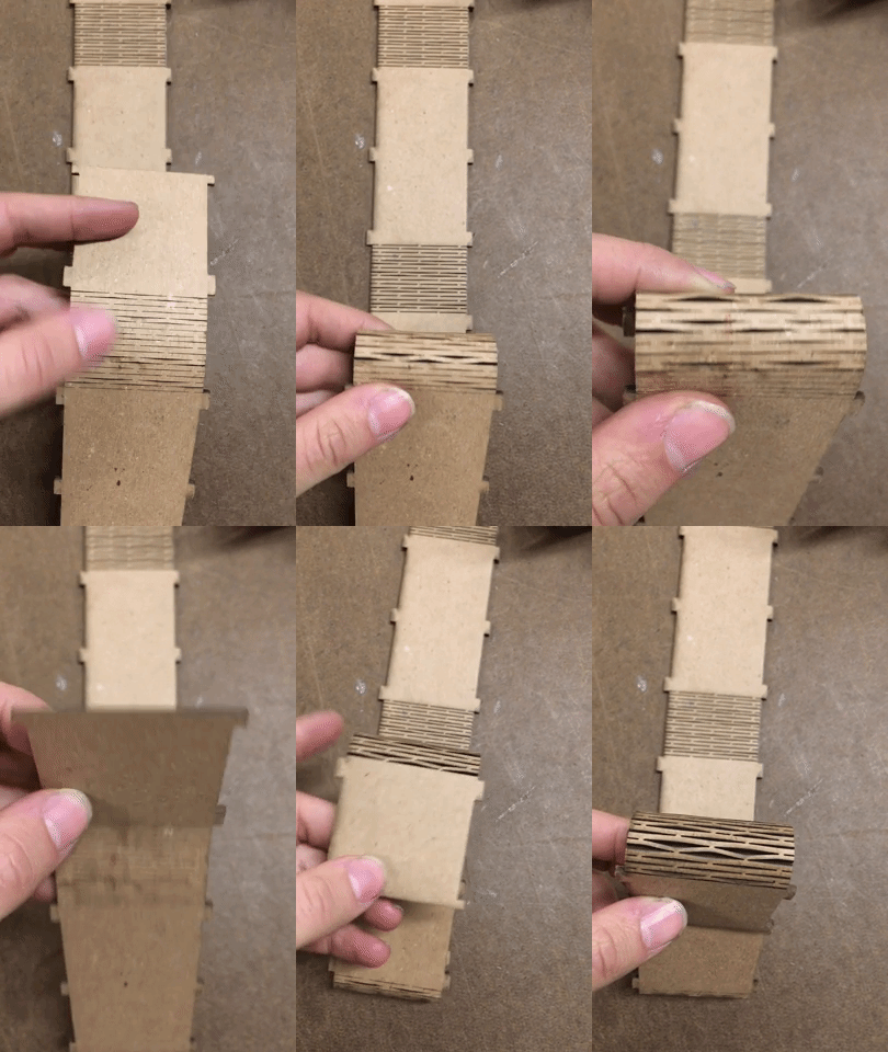
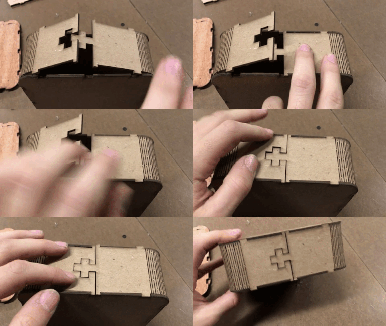
Once I had the first prototype assembled, I noticed that the two half panels where the hinged strip joined together tended to fly open if they weren’t held together in some way, so I decided to add a simple t-shaped mechanism to hold them together.
Next, I tried to switch to 1/4” plywood, but as I mentioned earlier, the living hinges just snapped in half when I tried to bend them.
Physical Computing Final Project Plan
Description
My final project for Physical Computing will be a drum glove for coming up with beats on the go. The glove will use flexible force-sensitive resistors made from velostat and conductive fabric in the glove’s fingertips to detect when the user taps on a surface. Taps will be translated to MIDI notes, which will be sent out over Bluetooth to either a smartphone or a computer that will play the MIDI notes as various kinds of drum samples. The glove will be powered by a rechargarble lithium ion polymer battery.
There may also be an interface for configuring the notes that each finger corresponds to, if user testing suggests that it’s necessary and I can come up with a satisfactory design.
Timeline
11/5 - 11/12:
- Playtest simple prototype
- Design note-changing interface
- Order materials
- Begin fabrication of first prototype (without bluetooth or battery)
- Practice sewing
11/13 - 11/20:
- Finish fabrication of first prototype (no bluetooth or battery)
- Decide on audio software (Smartphone app vs. DAW running on a laptop)
- Test with users
- Redesign sensor layout and interface if necessary
- Choose different glove material based on feedback from user testing
11/21 - 11/26:
- Fabricate version with bluetooth and battery, incorporating feedback from first prototype
- Test with users
- Decide on drum samples that will be used when demoing the project
11/27 - 12/4:
- Fabricate final version, incorporating feedback from second prototype
- Document design, fabrication, and testing process
12/5 - 12/13:
- Prepare for final presenatation
Testing Plan
For my initial round of user testing, I’m thinking of doing the following:
Ask testers to demonstrate how they would play the drums (any beat of their choosing) using their hands. This will hopefully give me some idea of which gestures and motions I’ll need to account for when placing sensors on the glove.
Give testers a pair of headphones, play a few different genres of drum beats (rock, jazz, house, etc.), and ask them to tap along to each beat with their hands. This will hopefully show me how people would play different kinds of drums (bass, snare, hi-hat) using their hands.
Repeat the last question, but with the added constraint that testers can only use individual fingers to play beats.
Explicitly ask how testers would play different kinds of drums (bass, snare, hi-hat) using their hands.
Bill of Materials
Bill of Materials (Google Spreadsheet)
System Diagram
Bookends
For the second week of Intro to Fabrication, we were asked to make multiples (5 or more) of something, and I chose to make bookends.
References
I used this Simple DIY Bookends guide to help me figure out my materials, measurements, and process.
Materials
- Pine boards: 6 1x6x4-1/2 pieces and 6 1x6x7 pieces (1 of each for each bookend)
- Rubber bumpers with adhesive backing: 2 packs of 16 (4 bumpers for each bookend)
- #10x1-1/4 phillips flat head screws: 3 packs of 8 (3 screws for each bookend)
Tools
- Miter saw
- Center punch
- Drill and 9/64 bit
- Phillips head screwdriver
- 90° corner clamp
- Speed clamp
- Sanding block
Process
For the following process, I first built one bookend all the way through, and once I understood how it was all going to work, I went back to the beginning and performed each step for all of the bookends at a time before moving on to the next.
Cutting the Pine Board
Step 1 was to cut the pine board into individual pieces. I used the miter saw to do this, along with a stop block that I set up using the miter saw’s builtin clamp and some scrap wood from the shop.
Fastening
Once the pieces were cut, I had to put them together. Initially, I thought that I was going to use a combination of wood glue and screws, but the wood glue ended up being messy (because I didn’t know what I was doing) and impractical (because it turned out that my pine boards had a significant curve which prevented the glue from adhering evenly).
Once I realized that the wood glue wasn’t going to work out, I decided to just skip it and only use screws. Before I drilled pilot holes for the screws, I used a ruler and a center punch to mark where the pilot holes should go.
I then used the drill to drive screws into the pilot holes, but used a screwdriver to tighten the last few turns to avoid stripping the screw or cracking the wood.
Rubber Bumpers
The next step was to attach rubber bumpers to the bottom of the bookend, to keep it from sliding around. The bumpers were self-adhesive; all I had to do to attach them was remove their paper backing and stick them to the wood.
L-brackets
I experimented with attaching two L-brackets to the front of one of the bookends (the “first pancake” that I tried to glue) because the guide that I was following suggested it. However, I didn’t really like how the brackets looked and they didn’t seem to make a difference for holding up books, so I didn’t add them to any of the others.
Sanding
The last step was to sand away any rough edges by hand, using a sanding block.
Results
Phyiscal Computing Final Project Ideas
Glove MIDI Controllers
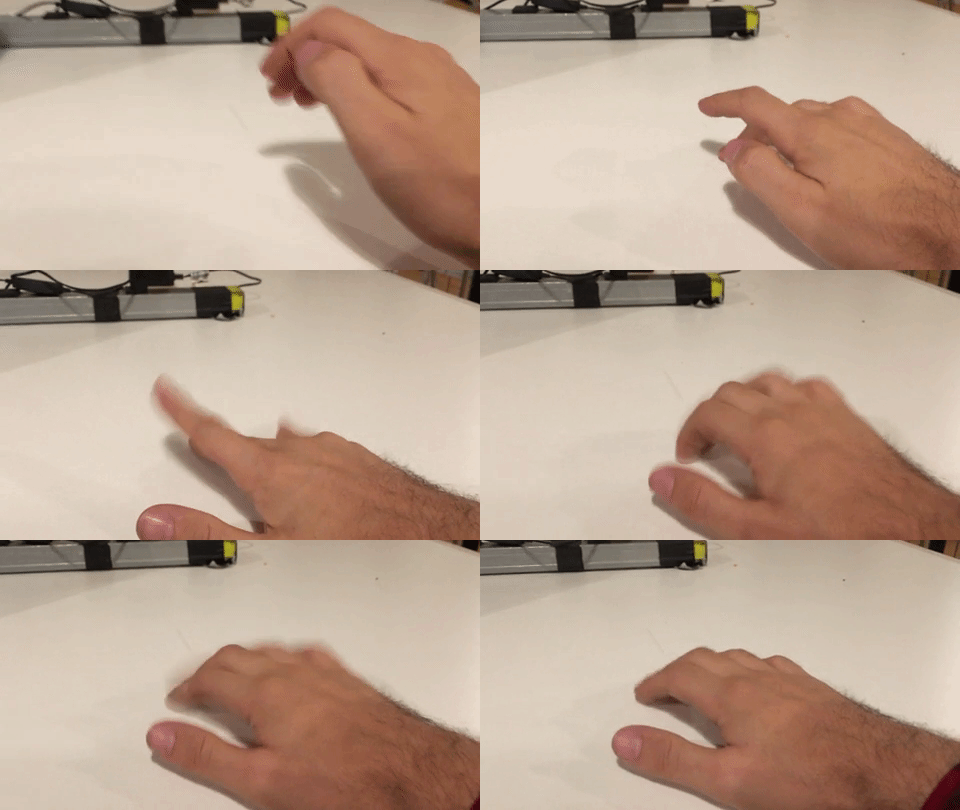
One idea that I’ve been thinking about, straight out of Phyiscal Computing’s Greatest Hits, is a pair of MIDI controller gloves. One glove would control drum beats via tapping:
The other glove would control the pitch of synth pad notes by sliding your fingers across a surface:
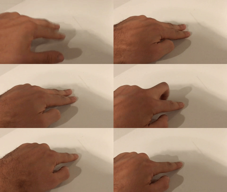
I’m imagining that the synth glove would trigger a note continuously while your finger was in contact with a surface, even if you weren’t sliding your finger to change the pitch. I still need to do some research to determine whether I’d need additional sensors beyond force-sensitive resistors to sense a sliding motion.
I’d also like to provide some sort of visual and/or haptic/rumble feedback to user when notes are triggered. Visual feedback could be something like LEDs near the fingertips that light up when notes are triggered.
I’d also like to make these gloves wireless if possible, so I’d have to look into sending MIDI data over Bluetooth or WIFI.
It might be unrealistic to try to make two working gloves in time for the final, in which case I would just pick one of the two to work on, but I like the idea of a pair that can be combined to play rhythm and melody simultaneously.
I also think that this project would benefit from collaboration, as it’s pretty technically complicated in scope.
Drawing Machine
Another idea that I’ve been thinking about is building a wall-mounted tension-controlled drawing machine, in the vein of Jürg Lehni’s Hektor and Viktor projects.
However, in order for this to qualify as a Physical Computing final project, I would need to come up with a way to make it physically interactive.
One way to make it interactive could be to use a Kinect and/or computer vision to detect the contours of a person’s body or face, and have the machine draw those contours, adjusting the drawing if the person moves. So, if you were to stand perfectly still, the machine would draw you accurately, but if you moved, you’d end up with a distorted drawing.
This is also a technically complicated project that would benefit from collaboration.