For the fourth week of Intro to Fabrication, we were asked to make a project enclosure, and…I went a little crazy with this assignment. In class, Ben mentioned powder-coated aluminum guitar pedal enclosures as a possibility, and I got really excited, because I’ve been playing guitar for most of my life, and it never occurred to me that I could make my own effects pedals.
I decided to make a 4-track audio looper pedal. The interface includes 4 stomp switches to control recording and playback for each loop track, 4 NeoPixel LED rings to show playback progress for each loop, a volume knob, another stomp switch for turning the pedal on and off, and an LED for indicating on/off status. I also intended to add two 1/4” mono audio jacks for input and output and a 9V power jack, but I ran out of time and wasn’t able to drill the necessary holes before class.
The case of the enclosure is powder-coated aluminum, but the lid of the enclosure is laser-cut acrylic, because I wanted to prototype my interface design before irrevocably drilling any holes in the powder-coated aluminum lid.
I consider this project half-done – I got overly ambitious with this, especially because I had to go home for Thanksgiving break and didn’t have access to the shop until the Monday before class.
Files
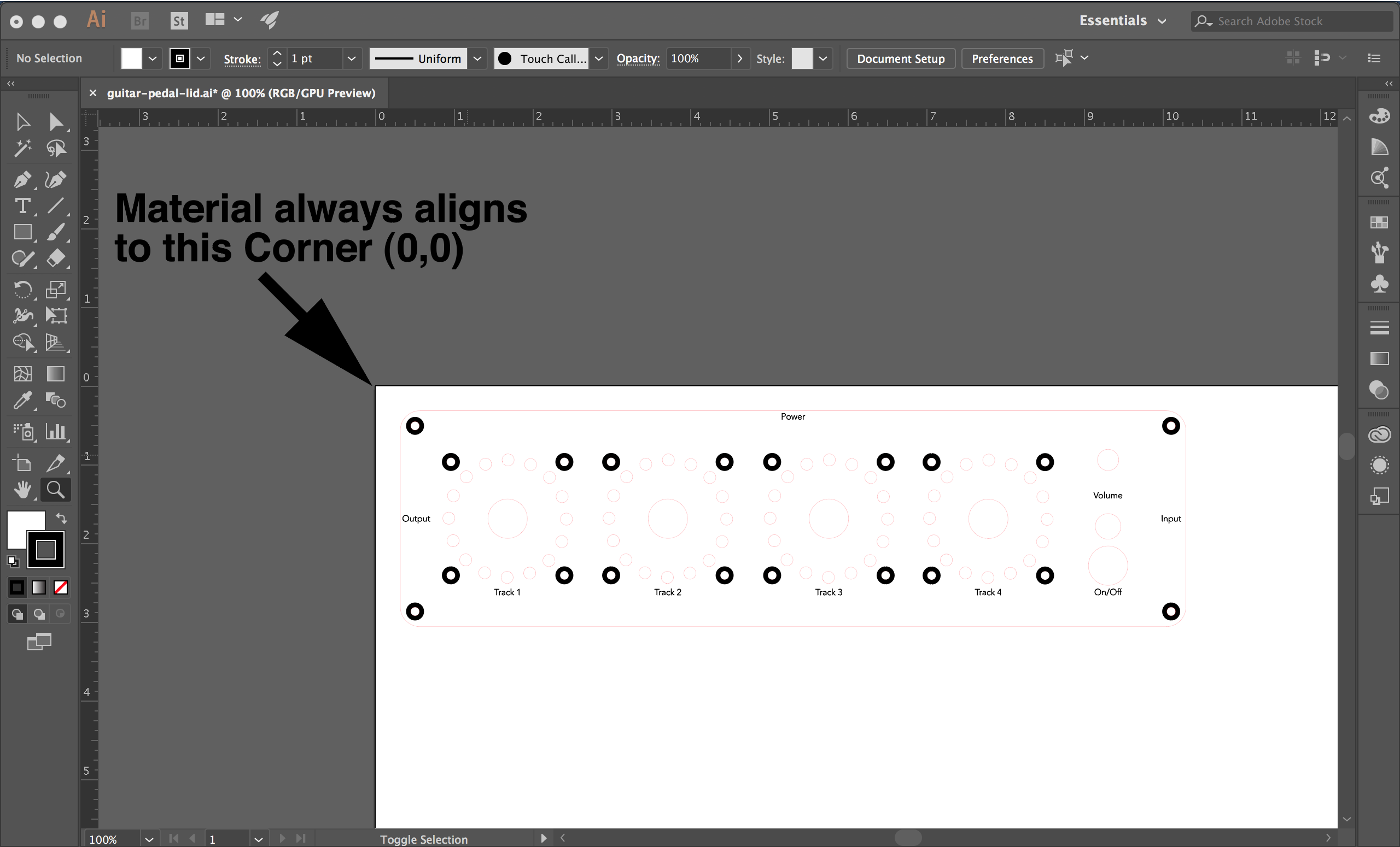
Illustrator file for laser cutting/etching the enclosure lid
STL file for 3D printing the NeoPixel ring mount
UPDATE: I redesigned the NeoPixel ring mount to prevent the ring from rotating.
Materials
- 1 Blemished Powder Coated Aluminum Enclosure
- 1 3PDT True Bypass Pedal Switch
- 4 DPDT Pedal Switches
- 1 10K Potentiometer
- 1 Pointer Knob
- 1 Panel Mount DC Power Jack
- 2 Panel Mount Mono 1/4” Audio Jacks
- 4 Pack of Rubber Feet
- 1 5mm LED Bezel
- 1 5mm Red LED
- 4 Adafruit NeoPixel 16 LED Rings
Process
The aluminum enclosure came with a set of countersunk screws, but I didn’t want to use those with an acrylic lid as that would require drilling into the acrylic with a countersink bit. Instead, I decided to use socket cap hex screws which would hopefully sit flush with the acrylic lid. I measured the original screws with a caliper (although now I know that I should have used a thread pitch gauge) and found that they were 10mm M3 screws, and then I went to Home Depot and bought the equivalent socket cap screws.
3D Printing
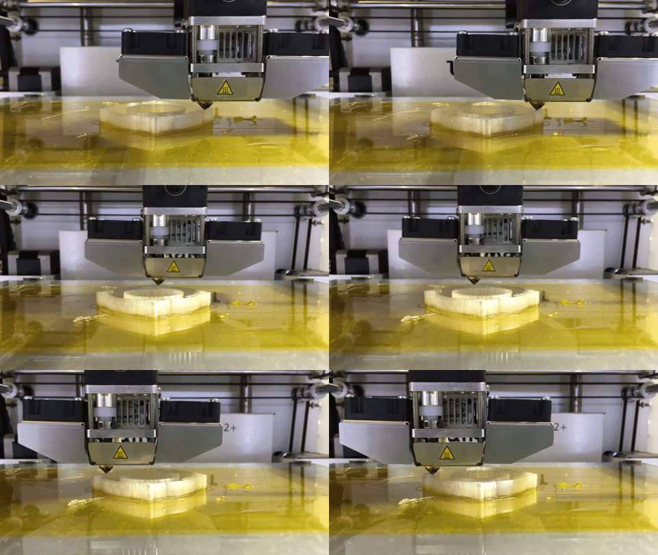
While waiting for my components to arrive, I started working on a 3D printed mounting bracket for the NeoPixel LED rings. I wanted to mount the NeoPixel rings underneath the lid, to prevent damage to the LEDs when a user steps on the pedal switches. I adapted these two designs from Thingiverse into a model with M3 screw holes, to re-use the screws that I’d already bought.
![]()
![]()

Designing the Interface
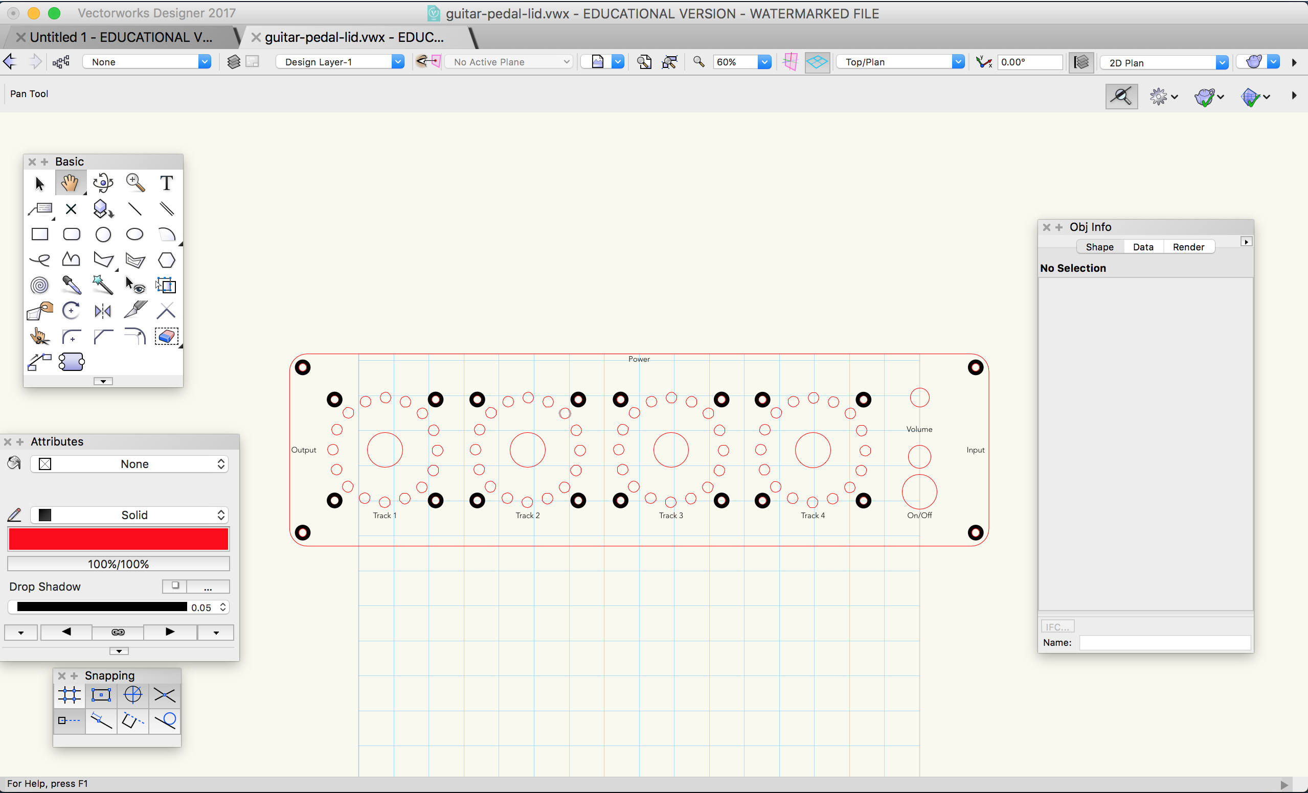
Once all of my components arrived, I measured the dimensions of the enclosure lid using a caliper, as well as the diameters of the switches, potentiometer, and LED bezel. I also found a data sheet for the enclosure that I checked my measurements against. I then used these measurements to make a laser cut design in Vectorworks.


Laser Cutting
I had to do a few test cuts in cardboard in order to get the placement of all of the screw holes exactly right.
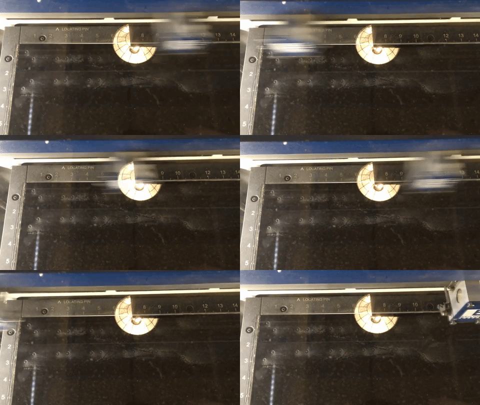
Once I had all of the holes positioned correctly, I did a cut in black acrylic. One mistake that I made here was to take the paper off of the acrylic before cutting & etching – this led to smudges from dust created by etching. In my design, I intended to etch a ring around each screw hole to allow the screw heads to recess into the lid, but in practice I found that the etching was time-intensive and didn’t lead to great results.

Putting it Together
Finally, I attached all of my panel-mount components and my NeoPixel ring mounts.
Next Steps
My next steps for this project would be to drill holes in the aluminum enclosure for the audio and power jacks, to playtest the interface design, to redesign the NeoPixel mounts to prevent the rings from sliding around, and eventually to re-do the interface in the original aluminum lid.